Input device configuration and calibration
This section provides instructions on how to configure your input device for the aircraft simulated in last_letter. This is required if you intend to control them manually. If you expect the aircraft control inputs to be generated by a controller (such as the arduipilot SITL), you don’t have to perform the following steps.
The ROS joy package
last_letter uses the joy ROS package to interface with input devices, which include many joysticks and gamepads. If your device can be read by joy, you can use it to control your aircraft in last_letter. However, configuration is required.
By default, joy expects to find the input device as /dev/input/js0. If your device is not mounted there, you should refer to this tutorial. If your device is in another jsX port, then you can change accordingly this line
<param name="dev" value="/dev/input/js0" />
in the last_letter/launch/simulation.launch file.
Configuration procedure
By following the configuration procedure, you will edit the /last_letter/data/parameters/HID.yaml file according to your input device. Open this file in your favourite text editor now. Comment out all lines and prepare a new device configuration by copying the provided template and un-commenting it.
Next, raise a ROS core, by typing in a terminal:
roscore
In a new terminal, type
rosrun joy joy_node
The output should be something like
[ INFO] [1431444728.249336803]: Opened joystick: /dev/input/js0. deadzone_: 0.050000.
Open yet another terminal and type
rostopic echo /joy
Move a control stick in your device to publish some messages. They should look like
header:
  seq: 409
  stamp:
    secs: 1431444879
    nsecs: 354395104
  frame_id: ''
axes: [0.0, 0.0, 0.6527636051177979, 0.0, -0.0]
buttons: [0, 0, 0]
Notice that the /joy topic has an axes and a buttons field, which will have variable size, depending on your device. These fields are zero-based arrays.
In the following section, you will re-map your device axes to match the following order of the virtual PWM input, which last_letter passes to the physics model. Each aircraft model assigns the PWM channels individually in its .yaml parameter files, but for airplanes in general the channel order is aileron, elevator, throttle and rudder.
Move the stick that corresponds to the channel 0 at full deflection; for airplanes, this usually is the one which controlls the roll axis, in the direction which rolls your aircraft to the right. Take a note of the (zero-based!) index of the axes array element that changed and its value. This value should normally be between -1 and 1. Copy the index at the /HID/axes[0] array element and the value at the /HID/throws[0] array element.
Do the same for channel 1 (elevator axis), by giving full deflection in the direction that pitches the aircaft upwards, and filling the /HID/axes[1] and /HID/throws[1] entries.
Do the same for the channel 2(throttle axis), by opening the throttle at its maximum throw and filling the /HID/axes[2] and /HID/throws[2] entries.
Do the same for the channel 3 (rudder axis), by giving full deflection towards the direction that yaws your aircraft to the right. Fill the entries /HID/axes[3] and /HID/throws[3].
Leave the /HID/buttons array and the rest of the /HID/axes and /HID/throws elements intact. They do not need to change for basic RC flight.
The input device configuration procedure is complete.
Supported devices
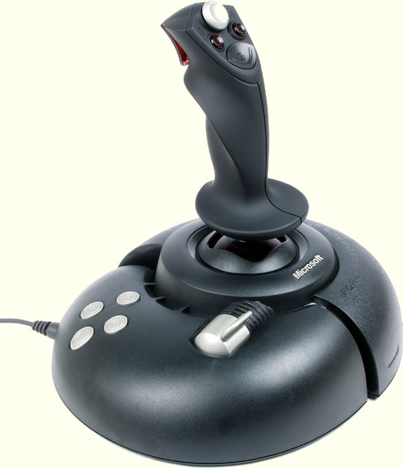
So far the following devices have been successfuly tested with last_letter: * Microsoft SideWinder 2 joystick
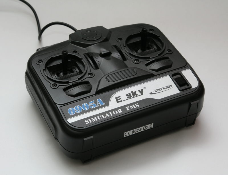
- E-Sky 0905A USB Transmitter
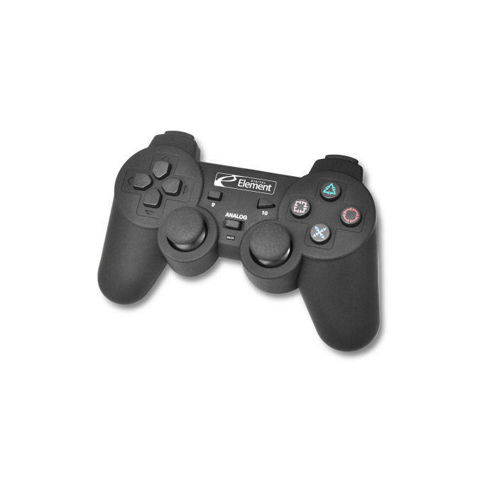
- Digital Element GM-400
Configuration parameters for those devices can already be found on the HID.yaml file. In order to use them, leave only the corresponding lines uncommented.
Mixing support
There is some rudimentary support for channel mixing, for the case of more complex aircraft or multirotors. You can enable a mixing scheme by uncommenting the /HID/mixerid parameter in the HID.yaml parameter file. Currently, there are 3 types of mixers implemented.
0: No mixing - the aircraft model will receive the channels exactly as they are remapped and scaled by the calibration procedure.
1: Airplane mixing - The throttle channel will be re-scaled from [-1 1] to [0 1] to be used by a motor and channel 0 will be also be mapped from [-1 1] to [0 1], in order to suitably control the simulation reset function.
2: Quadrotor mixing - The first 4 channels are mixed with each other to produce meaningful motor signals for an X-frame quadrotor. A reset channel is also configured.
3: Firefly Y6 mixing - Mixing suitable for a somewhat clunky control scheme of the Firefly Y6 hybrid vehicle.
You can add more mixing schemes by yourself in the last_letter/last_letter/src/joy2chan.cpp file. Re-compilation of the code is required.